Specifications
- Maximum Capacity (Flow Rate) – 900m³/h (4000 USgqm)
- Differential Head – 150 mLC (500 ft)
- Maximum Allowable Working Pressure – 35 bar at 200°C (500 psi at 390°F)
- Maximum Transmissible Power – 195 kW (265 HP) at 3500 rpm160 kW (217 HP) at 2900 rpm
- Maximum Fluid Temperature – 50°C (485°F)400°C (750°F)
Containment Information
| Containment shell The containment shell is a designed pressure vessel to separate the pumped liquid from the atmosphere only. The shell is not used as an additional bearing holder. Therefore, no dynamic stress occurs.Besides the standard containment shell with can, made in one piece, a containment shell of “sandwich design” is also available. This design will be applied at pump speed 2900/3500 rpm and motor ratings above 75 kW in order to reduce magnetic losses. Different from the conventional design, this sandwich containment shell consists of two shells. The inner shell which accepts the radial loads consists of centered rings. These rings are insulated from each other by confined Gore-Tex-PTFE gaskets and preloaded by a wave spring to avoid any leakage. The outer shell consists of a slotted pipe with bottom and adapter flange welded to it. This shell accepts the axial loads generated by the pressure p5. This design – together with a special magnet assembly – reduces the magnetic losses by approx. 50%, compared to a Hastelloy C containment shell of 1.0 mm (0,039″) thickness. The maximum allowable working pressure is 35 bar at 200°C (500 psi at 390°F).Containment shell protection / Internal clearances The clearance between the rotating drive magnets and the stationary containment shell is larger than the clearance between the rotating safety ring and the bearing bracket. This prevents containment shell rupture in case of ball bearing failure. Due to the radial clearance S2 > 1,25 mm the pumps can handle non-metallic (non-ferrous) particles in the fluid up to 1,0 mm.Secondary containment |
Bearing Information
| Double sleeve bearings The pump shaft is carried by two sleeve bearings. These bearings are located in the pumped liquid. Bearing material is pure alpha grade Silicon Carbide. SiC is corrosion proof to all kinds of acids and hydroxides and suitable for all common pumped liquids. Extreme hardness and wear resistance accept also abrasive solids. An additional “diamond like Carbon coating” reduces friction losses and accepts dry running conditions until monitoring device will switch off the unit. The SiC-bearing parts are shrink-fitted in metallic holders or elastically beared by metallic tolerance rings. This protects the bearing unit against shock or thermal stress, caused by different thermal expansion of metal und ceramic. Design temperature is 400°C. Both stationary sleeve bearings are located in the common bearing housing which guarantees absolute centricity.Antifriction bearings The outer magnet shaft is fitted with generously dimensioned antifriction bearings. The bearings are L10 rated for an average life in excess of 3 years. The oil bath is protected against the atmosphere by a replaceable labyrinth seal. Oil level is controlled by a constant level oiler and additionally by a bull’s eye sight glass. Oil mist lubrication available as an option. |
Additional Information
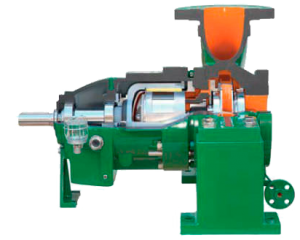
| Construction The PRM-pumps are end suction, top discharge, single stage, radial split volute casing pumps of back-pull-out design with closed impellers. The mechanical design meets the API 685 requirements. The bearing bracket design allows the removal of the complete unit including outer magnets and ball bearings without depressuring the pump or exposing the pumpage to the atmosphere.Volute casing The volute casing of standard design is cast en bloc and centerline supported. The casing forms – together with the containment shell – the pressure retaining pump unit. Maximum allowable pressure at PT is determined by the shell design and the material. The pump casing has metal-to-metal fits with confined compression controlled gaskets. Pump flanges are full or spot faced on the back and designed for through-bolting.Magnetic coupling Mating wear surface materials have a difference in Brinell hardness of at least 50 HB.Monitoring |


